Lab2 Pseudo Random Binary Sequence (PRBS) Generation.
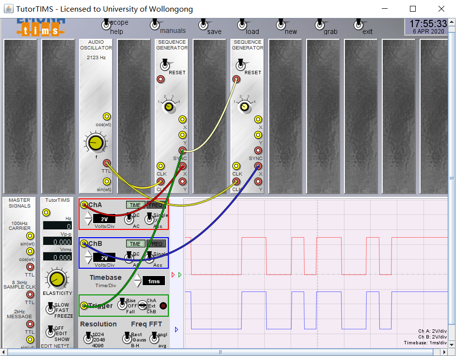
Section 1: Displaying PRSB Using the ‘Snapshot’ Method
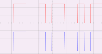
task1 Examination of Sequence Generator


increase the length of bits switching to ‘4’ from ‘1’
task2 Band limiting


3dB frequency (WIDE position)
$$
{288659/360 =801.830 HZ}
$$
3dB frequency (NORMAL position)
$$
{577318/860 =335.65 HZ}
$$
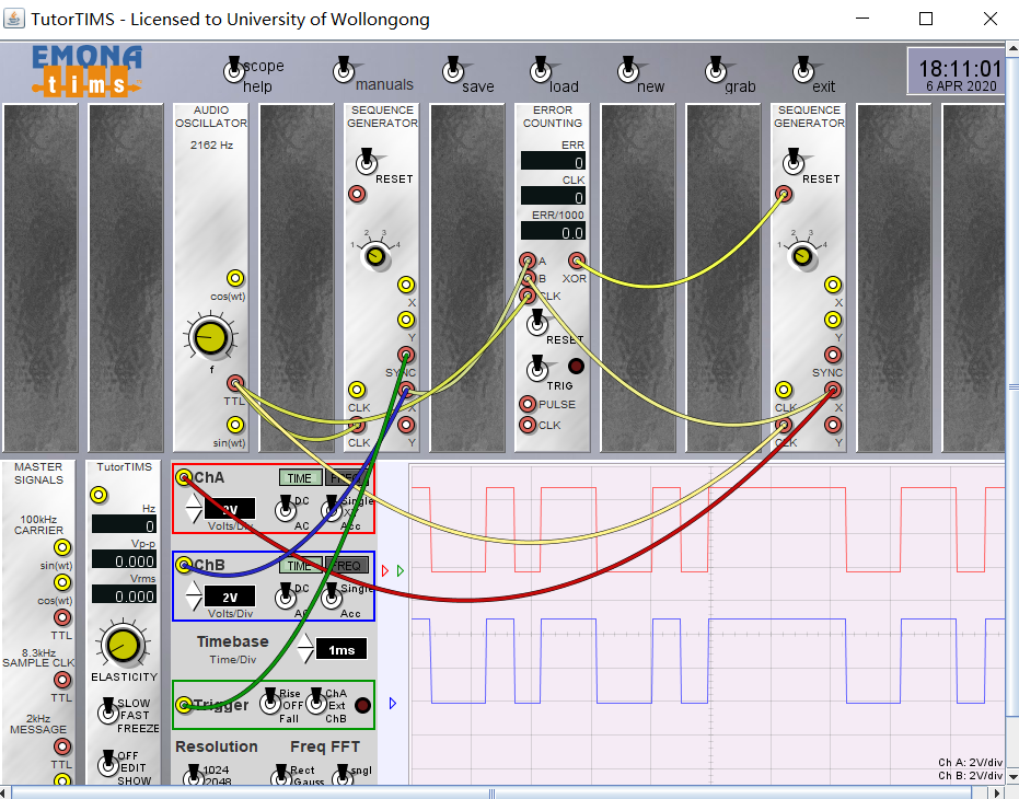
Section 2 Two Generators Alignment


the generator will remain the state(aligned) until doing next reset action
The sequences would be offset by the time delay
Section 3: Two Sequence Alignment
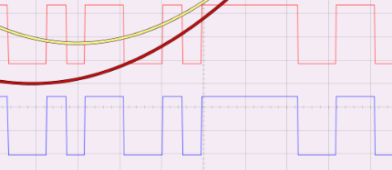
task1 The Sliding Window Correlator


Once alignment has been achieved, it will be maintained even **
**when the RESET signal to the receiver generator is broken.
Tutorial Question
Q1:you have seen the first ‘n’ bits of a sequence, using the start-of-sequence signal to initiate the oscilloscope sweep. How could you show the next ‘n’ bits of the same sequence? Can you demonstrate your method with TIMS? (Hint: you need to delay the SYNC pulse – think about a feature of the oscilloscope or using features of the TWIN PULSE GENERATOR as described in its data sheet).
Q2: estimate the bandwidth of the sequence as a function of bit rate clock frequency. Describe a method for estimating the maximum rate at which a binary sequence can be transmitted through a low-pass filter. Relate its predictions with your observations. (Hint: at what rate will a rectangular pulse retain its approximate ‘shape’?)
Q3:explain what is meant when two sequences are ‘synchronised’ and ‘aligned’.
Q4: was there any obvious misalignment between the TTL sequence input to, and the bandlimited sequence output from, the TUNEABLE LPF? Explain.
Q5: in the last model examined, explain why the sequence alignment takes longer when the sequence length is increased.
Q6: suppose the TIMS SEQUENCE GENERATOR is driven by an 8.333 kHz TTL clock. What would the TIMS FREQUENCY COUNTER read if connected to the output sequence? Explain.(Hint: Remember that the sequence is random and the best case is that 50% of pulses will be ‘1’’s and 50% will be 0’s and the frequency counter will only count only when there is a clock pulse and a ‘1’ is transmitted – we expect a much lower count as a result).
Q7: what should an rms meter read if connected to a TTL pseudo random binary sequence ?
Q8 :with a 2.083 kHz clock what is the delay, for a 2048 bit sequence, between consecutive displays ? (Hint: delay is number of bits in a repeated sequence times the clock frequency resulting in a time in seconds which will be the delay)